The 2018 Suzuki Battery Isolator Lead ensures efficient dual-battery charging, operating within 13.5-14.5 volts. It safely isolates and regulates power distribution, preventing overvoltage and ensuring system reliability.
1.1 Overview of the Suzuki Battery Isolator System
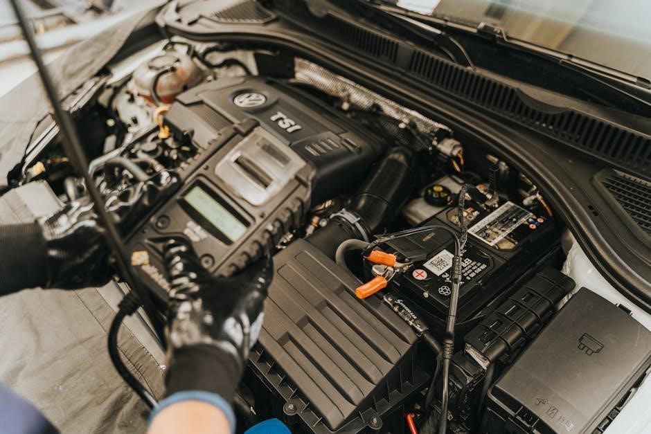
The Suzuki Battery Isolator System is designed to manage dual-battery setups efficiently, ensuring safe and reliable power distribution. It operates within a voltage range of 13.5V to 14.5V, ideal for charging auxiliary batteries without risking overcharge or system instability. The system uses high-quality components, including diodes and insulated wiring, to isolate the starting and house batteries, preventing reverse current flow. This setup allows simultaneous charging of both batteries while protecting sensitive electronics. The isolator lead plays a crucial role in maintaining voltage stability, ensuring consistent power delivery to all connected systems. Its compact design and durable construction make it suitable for marine applications, aligning with Suzuki’s commitment to performance and reliability in outboard motor systems.
1.2 Importance of Voltage Output in Battery Isolation
The voltage output in the Suzuki Battery Isolator Lead is critical for maintaining optimal battery performance and system safety. Proper voltage regulation ensures that both the starting and auxiliary batteries receive the correct charge, preventing overcharging or undercharging scenarios. A steady voltage output within the 13.5V to 14.5V range is essential for prolonging battery lifespan and preventing damage to electrical components. Incorrect voltage levels can lead to reduced charging efficiency, premature battery degradation, or even system failure. By maintaining precise voltage control, the isolator lead safeguards the dual-battery setup, ensuring reliable engine starting and consistent power supply to onboard systems. This voltage stability is vital for the overall performance and longevity of the marine electrical system.
1.3 Purpose of the PDF Documentation
The PDF documentation for the 2018 Suzuki Battery Isolator Lead is designed to provide comprehensive technical details and operational guidelines. It serves as a reference for understanding the isolator lead’s voltage output specifications, proper installation, and maintenance procedures. The document outlines safety protocols, wiring diagrams, and troubleshooting steps to ensure optimal performance. It also clarifies the compatibility of the isolator lead with Suzuki outboard motors and auxiliary battery systems. By following the PDF guide, users can achieve efficient dual-battery charging while adhering to safety standards and manufacturer recommendations. This resource is essential for both professionals and DIY enthusiasts to maximize system reliability and longevity. It ensures seamless integration and operation of the isolator lead in marine applications.

Key Specifications of the 2018 Suzuki Battery Isolator Lead
The 2018 Suzuki Battery Isolator Lead operates at 13.5-14.5 volts, supporting 12V lead-acid batteries. It ensures compatibility with Suzuki outboard motors and auxiliary systems, optimizing dual-battery charging efficiently.
2.1 Maximum Voltage Output Range
The maximum voltage output range for the 2018 Suzuki Battery Isolator Lead is specified between 13.5 and 14.5 volts. This range is critical for ensuring safe and efficient charging of both the main and auxiliary batteries. Operating within this range prevents overcharging, which can damage batteries and connected systems. The isolator lead is designed to maintain stable voltage levels, even under varying load conditions, ensuring reliable performance. This voltage range aligns with the alternator’s output, making it ideal for dual-battery setups in Suzuki outboard motors. Proper voltage regulation within this range is essential for longevity and optimal functionality of the entire electrical system.
2.2 Recommended Battery Type and Capacity
Suzuki recommends a 12-volt cranking-type lead-acid battery for optimal performance with the 2018 Battery Isolator Lead. The minimum battery requirement for starting the engine is 650 Marine Cranking Amps (MCA)/ABYC, 512 Cold Cranking Amps (CCA)/SAE, or 160 Reserve Capacity (RC) Minutes/SAE. This ensures reliable starting and consistent power delivery. While lithium batteries can be used, caution is advised, as the Suzuki manual highlights specific considerations for their implementation. The battery must meet these specifications to ensure compatibility with Suzuki outboard motors and maintain the isolator lead’s efficiency in dual-battery systems. Proper battery selection is crucial for system reliability and longevity.
2.3 Compatibility with Suzuki Outboard Motors
The 2018 Suzuki Battery Isolator Lead is specifically designed for compatibility with Suzuki outboard motors, including the DF100A, DF115A, DF140A, DF150A, DF175A, and DF200A models. This ensures seamless integration and optimal performance when charging auxiliary batteries. The isolator lead is engineered to work in harmony with Suzuki’s alternator system, providing consistent voltage output and preventing cross-charging between batteries. Proper installation, as outlined in Suzuki’s documentation, guarantees reliable operation and compatibility across the range of Suzuki outboard motors. This compatibility ensures efficient charging and power distribution, making it an essential component for dual-battery setups in Suzuki-powered vessels.
Understanding Voltage Output in the Isolator Lead
The 2018 Suzuki Battery Isolator Lead delivers a regulated voltage output between 13.5 and 14.5 volts. This range ensures efficient charging of both primary and auxiliary batteries while preventing overvoltage damage. The isolator lead’s voltage output is critical for maintaining battery health and system reliability, especially in marine applications where consistent power delivery is essential. Proper voltage regulation prevents battery drain and ensures safe operation of electrical components. This voltage range aligns with Suzuki’s alternator specifications, making it ideal for dual-battery setups in outboard motors. Understanding and monitoring this voltage output is vital for optimal performance and longevity of the electrical system.
3.1 Maximum Output Voltage Specifications
The 2018 Suzuki Battery Isolator Lead operates with a maximum output voltage range of 13.5 to 14.5 volts. This specification ensures safe and efficient charging of both the main and auxiliary batteries. Exceeding this range could damage the electrical system or batteries. The isolator lead is designed to regulate voltage, preventing overcharging and maintaining stability. This range aligns with Suzuki’s alternator output, ensuring compatibility and optimal performance. Proper voltage regulation is crucial for preventing battery degradation and electrical component failure. Monitoring this range helps maintain system reliability, especially in marine environments where consistent power delivery is essential. Adhering to these specifications ensures longevity and functionality of the dual-battery setup.
3.2 Minimum Voltage Requirements for Charging
The minimum voltage required for charging with the 2018 Suzuki Battery Isolator Lead is approximately 12.7 volts. This threshold ensures the isolator lead can effectively initiate and maintain charging of the auxiliary battery. Failure to meet this minimum voltage may result in undercharging or incomplete charging cycles. The isolator lead is designed to prevent battery drain by isolating the charging circuit when voltage drops below this level. This feature protects the starting battery from depletion while ensuring the auxiliary battery charges properly. Maintaining this voltage range is critical for system functionality and battery longevity, especially in marine applications where consistent power delivery is essential for reliable operation. Monitoring voltage levels ensures optimal performance and prevents potential electrical system issues.
3.3 Voltage Regulation and Stability
Voltage regulation and stability are critical for the 2018 Suzuki Battery Isolator Lead to ensure reliable battery charging. The system is designed to maintain a consistent voltage output between 13.5 and 14.5 volts, preventing fluctuations that could damage electrical components. Advanced diodes and isolating circuits work together to regulate voltage, ensuring stable power delivery to both the starting and auxiliary batteries. This stability prevents overcharging or undercharging, which can extend battery life and enhance system performance. Proper voltage regulation also safeguards against electrical spikes or drops, protecting sensitive marine electronics. Monitoring voltage stability is essential to ensure the isolator lead functions within its specified range, maintaining optimal charging efficiency and overall system reliability.
Battery Recommendations for the Suzuki Isolator Lead
Suzuki recommends a 12-volt lead-acid battery with 650 MCA/ABYC or 512 CCA/SAE. Lithium batteries are compatible if configured correctly to match voltage and charging requirements.
4.1 Lead-Acid vs. Lithium Batteries
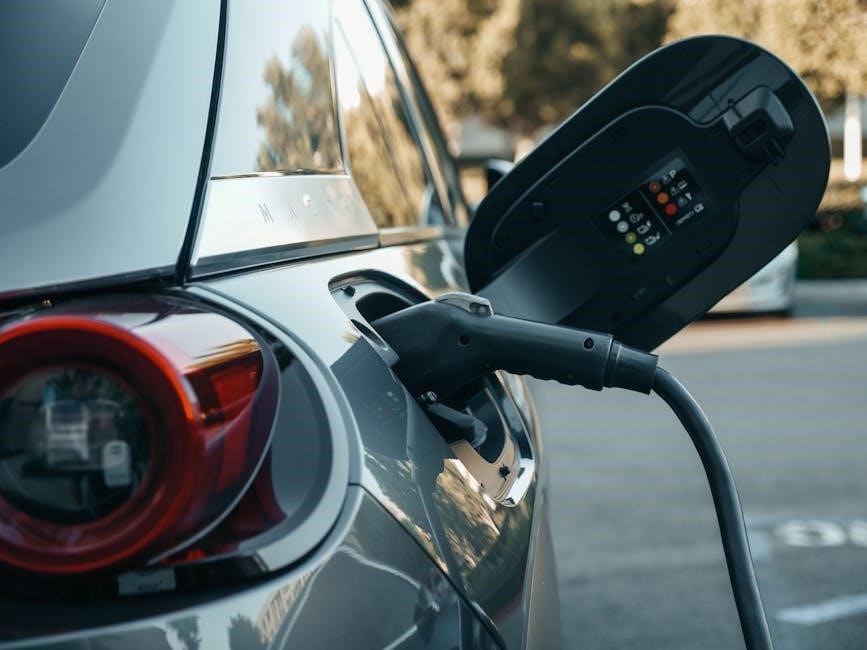
For the Suzuki isolator lead, lead-acid batteries are traditionally recommended due to their reliability and compatibility with the system’s voltage output. They meet specifications like 650 MCA/ABYC or 512 CCA/SAE, ensuring reliable engine starting. Lithium batteries, while efficient and lightweight, require careful configuration to match the isolator’s voltage range. Suzuki’s manual expresses caution with lithium, though users report success with proper setup. Both battery types must align with the isolator’s maximum output of 13.5-14.5 volts to prevent overvoltage or undercharging. Choosing the right battery depends on performance needs, weight considerations, and charging system compatibility. Always adhere to Suzuki’s guidelines for optimal performance and safety.
4.2 Cranking Amps (CA) and Cold Cranking Amps (CCA)
Cranking Amps (CA) and Cold Cranking Amps (CCA) are critical for selecting the right battery for the Suzuki isolator lead system. CA measures the battery’s ability to supply power during engine starting under normal conditions, while CCA reflects performance in colder temperatures. Suzuki recommends a 12-volt lead-acid battery with a minimum of 650 Marine Cranking Amps (MCA)/ABYC or 512 Cold Cranking Amps (CCA)/SAE. Higher-capacity batteries, such as 1000 MCA/ABYC or 800 CCA/SAE, may be required for larger outboard models. Meeting these specifications ensures reliable engine starting and proper charging through the isolator lead. Always verify the battery’s ratings align with Suzuki’s guidelines for optimal performance and system compatibility.
4.3 Reserve Capacity (RC) and Marine Cranking Amps (MCA)
Reserve Capacity (RC) and Marine Cranking Amps (MCA) are essential metrics for evaluating battery performance. RC measures the battery’s ability to supply power when the alternator is not charging, typically during extended periods with high accessory loads. MCA, specific to marine applications, indicates the battery’s capacity to deliver power in harsh, wet conditions. Suzuki recommends batteries with at least 160 Reserve Capacity (RC)/SAE or 650 Marine Cranking Amps (MCA)/ABYC. Higher MCA ratings ensure reliable starting and accessory operation in demanding marine environments. Selecting a battery with sufficient RC and MCA ensures consistent power delivery and compatibility with the Suzuki isolator lead system, optimizing both starting performance and auxiliary power needs.
Wiring and Installation Guidelines
Proper wiring ensures safe and efficient charging. Connect the auxiliary lead directly to the house battery, avoiding overvoltage risks. Always use high-quality cables and follow Suzuki’s specifications for installation.
5.1 Connecting the Auxiliary Battery Lead
Connecting the auxiliary battery lead requires careful attention to ensure proper function and safety. Begin by identifying the positive terminal of the auxiliary battery and the corresponding lead from the isolator. Use high-quality, appropriately gauged wire to connect the lead to the auxiliary battery, ensuring minimal resistance and voltage drop. Install a fuse or circuit breaker inline to protect against overcurrent conditions. Refer to the Suzuki manual for specific wiring diagrams and recommendations. Proper connection ensures efficient charging and prevents damage to the electrical system. Always follow safety guidelines and double-check connections before powering up the system.
5.2 Proper Wiring to the House Battery System
Proper wiring to the house battery system ensures seamless integration with the Suzuki isolator lead. Connect the isolator lead to the house battery’s positive terminal, using high-quality, marine-grade wire to minimize voltage drop. Install a fuse or circuit breaker close to the battery to protect against overcurrent. Ensure the wiring complies with ABYC standards for safety and reliability. The isolator lead should be routed away from heat sources and sensitive electronics to prevent interference. Verify that the voltage output matches the house battery’s requirements, typically between 13.5 and 14.5 volts. Consult the Suzuki manual for specific wiring recommendations and safety guidelines to avoid improper connections.
5.3 Fuse and Circuit Protection Requirements
Fuse and circuit protection are critical for safeguarding the 2018 Suzuki Battery Isolator Lead system. A 15A fuse is recommended for the sub-battery cable to prevent overcurrent and potential damage. Ensure the fuse is installed close to the battery terminal for optimal protection. Use marine-grade circuit protection components that meet ABYC standards to ensure reliability and safety. Proper circuit protection prevents overheating, electrical fires, and system failure. Always follow Suzuki’s recommended specifications for fuse ratings and installation. Avoid using higher-rated fuses than specified, as this could compromise safety. Regularly inspect the fuse and circuit connections for signs of wear or damage. Replace any faulty components immediately to maintain system integrity and performance.

Components of the Suzuki Battery Isolator Lead
The isolator lead includes diodes for electrical isolation, high-voltage wire harnesses, and durable connectors. These components ensure safe and efficient power distribution between batteries, preventing current recirculation.
6.1 Diodes and Their Role in Isolation
The diodes in the Suzuki Battery Isolator Lead are crucial for preventing electrical feedback between batteries. They act as one-way electrical checkpoints, ensuring that charge current flows only in one direction. This prevents the auxiliary battery from draining power back into the starting battery or the alternator. By isolating the circuits, diodes maintain system stability and prevent overvoltage conditions. They are typically mounted within an aluminum profile, enhancing heat dissipation and reliability. Proper diode operation is essential for safe and efficient dual-battery charging, ensuring that each battery is charged independently without interference.
6.2 High-Voltage Wire Harness and Connectors
The high-voltage wire harness and connectors in the Suzuki Battery Isolator Lead are designed to handle the system’s electrical demands safely. The harness is constructed with heavy-duty insulation to prevent overheating and ensure reliable power distribution. Connectors are built with corrosion-resistant materials, ideal for marine environments. Orange coloring on high-voltage components serves as a visual warning for safety. These components are engineered to maintain consistent voltage output and prevent electrical interference. Proper installation ensures secure connections, minimizing the risk of power loss or arcing. The high-voltage wire harness and connectors play a critical role in maintaining the integrity and safety of the isolator lead system.
6.3 Isolator Lead Assembly and Accessories
The isolator lead assembly is a crucial component, ensuring proper electrical isolation between batteries. Accessories include fuses, terminals, and mounting hardware, designed for durability and ease of installation. The assembly is pre-wired for compatibility with Suzuki outboard motors, simplifying setup. High-quality materials resist corrosion and withstand harsh marine conditions. Accessories like the sub-battery cable fuse (rated 15A) protect the system from overcurrent. The isolator lead assembly is compact, minimizing space requirements while maintaining functionality. Proper installation, as outlined in Suzuki’s guidelines, ensures optimal performance and safety. These components work together to provide a reliable dual-battery charging system, essential for uninterrupted power supply during marine operations.
Safety Precautions and Voltage Monitoring
Adhere to high voltage warnings and monitor output levels during operation to prevent overvoltage. Implement emergency shutdown procedures if voltage exceeds safe limits to ensure system and user safety.
7.1 High Voltage Caution and Warning Labels
The 2018 Suzuki Battery Isolator Lead features prominent high-voltage caution labels on components like the orange-colored wire harness and connectors. These labels emphasize the risks of high voltage exposure, ensuring users are aware of potential electrical hazards. Proper handling is crucial to avoid shocks or injuries. The labels comply with safety standards, highlighting safe practices when interacting with the system. Always follow the manufacturer’s guidelines to prevent accidents. The high-voltage components are clearly marked to alert users of the dangers associated with their operation and maintenance. Safety should never be compromised when working with electrical systems.
7.2 Monitoring Voltage Levels During Operation
Monitoring voltage levels during operation is critical for ensuring the 2018 Suzuki Battery Isolator Lead functions within safe parameters. The system operates between 13.5 and 14.5 volts, essential for proper charging of both the starting and auxiliary batteries. Exceeding these limits can lead to overvoltage, potentially damaging the electrical system. Regular voltage checks using a multimeter or voltage meter are recommended to maintain optimal performance. Additionally, the isolator lead’s design includes safeguards to prevent voltage spikes, ensuring reliable power distribution. Continuous monitoring helps identify issues early, such as faulty components or improper connections, preventing system failure. Always refer to the PDF documentation for detailed procedures and guidelines on voltage monitoring and maintenance.
7.3 Emergency Shutdown Procedures
In case of an overvoltage condition or system malfunction, the 2018 Suzuki Battery Isolator Lead is equipped with emergency shutdown procedures to protect the electrical system. If the voltage exceeds the specified range of 13.5 to 14.5 volts, the isolator lead will automatically disconnect power to prevent damage. Users should immediately switch off the engine and disconnect the auxiliary battery to avoid further issues. It is crucial to inspect the system for faults, such as faulty diodes or wiring, before restarting. Always refer to the PDF documentation for detailed shutdown steps and safety protocols. Following these procedures ensures the integrity of the battery isolator system and prevents potential electrical hazards. Regular maintenance and voltage monitoring can help prevent emergencies.

Troubleshooting Common Issues
Identify issues like low voltage output or overvoltage by checking diodes, wiring, and connections. Refer to the PDF for diagnostic steps and solutions to ensure proper function.
8.1 Low Voltage Output from the Isolator Lead
Low voltage output from the isolator lead can prevent proper charging of auxiliary batteries. Common causes include faulty diodes, worn-out wiring, or incorrect connections. Check the voltage at the isolator lead terminals using a multimeter. If readings fall below 13.5 volts, inspect the diodes for damage or corrosion. Ensure all connections are clean and secure. Additionally, verify that the battery meets the recommended specifications, such as 650 MCA or 512 CCA. If issues persist, consult the PDF documentation or contact a certified Suzuki technician for further diagnosis and repair to restore optimal voltage output and system performance.
8.2 Overvoltage Protection and Prevention
Overvoltage protection is critical to prevent damage to the battery and electrical systems. The isolator lead ensures voltage remains within safe limits, typically 13.5-14.5 volts. Excessive voltage can occur due to faulty voltage regulators, damaged wiring, or malfunctioning diodes. Symptoms include battery swelling, overheating, or system malfunctions. To prevent overvoltage, regularly inspect the isolator lead and associated components for damage or corrosion. Ensure proper wiring and connections, and consider installing a voltage monitor. If overvoltage is detected, disconnect the system immediately and address the root cause. Refer to the PDF documentation for specific troubleshooting steps and recommendations to safeguard the battery and electrical components from overvoltage-related damage.
8.3 Diagnosing Faulty Isolator Lead Components
Diagnosing faulty isolator lead components involves checking for signs of wear or damage. Inspect the diodes, wire harness, and connectors for corrosion or breaks. Use a multimeter to test voltage output; deviations from the 13.5-14.5V range indicate issues. If voltage is low, check connections and wiring for faults. For overvoltage, inspect the voltage regulator or isolator lead for malfunction. Replace any damaged components promptly to maintain system reliability. Refer to the PDF documentation for detailed diagnostic procedures and guidelines to ensure accurate troubleshooting and prevent further system damage. Regular maintenance and testing are essential to uphold the isolator lead’s performance and longevity.

Maintenance and Upkeep of the Isolator Lead
Regular cleaning and inspection of the isolator lead are vital to ensure optimal performance. Check for wear, corrosion, or damage and test voltage output annually. Refer to the PDF for detailed maintenance guidelines and procedures to prevent system issues.
9.1 Cleaning and Inspecting the Lead
Regular cleaning and inspection of the 2018 Suzuki Battery Isolator Lead are essential for maintaining its efficiency and longevity. Use a soft, dry cloth to wipe down the lead, ensuring no dirt or corrosion builds up on the connectors. Avoid using harsh chemicals or abrasive materials, as they may damage the components. Inspect the high-voltage wire harness and connectors for signs of wear, fraying, or discoloration. Check the diodes and isolator assembly for any visible damage or excessive heating. Ensure all connections are secure and free from corrosion. Perform voltage output tests annually to verify the system is operating within the specified 13.5-14.5 volt range. Address any issues promptly to prevent system malfunctions.
9.2 Replacing Worn or Damaged Components
Replacing worn or damaged components of the 2018 Suzuki Battery Isolator Lead is crucial for maintaining optimal performance and safety. Inspect the lead and its connectors regularly for signs of wear, such as fraying wires, corroded terminals, or cracked insulation. Replace any damaged components immediately to prevent electrical issues. Use only genuine Suzuki parts or equivalent replacements to ensure compatibility and reliability. When replacing the high-voltage wire harness or connectors, disconnect the battery to avoid electrical shock. If diodes or the isolator assembly are faulty, replace them with components meeting the specified voltage and current ratings. Consult a professional if unsure, and always follow proper safety protocols to prevent further damage or system malfunctions. Regular replacement ensures consistent voltage output and system reliability. Always test the system after replacement to verify proper operation within the 13.5-14.5 volt range; Addressing worn parts promptly safeguards the entire electrical system and maintains efficient charging of both batteries. Proper maintenance extends the lifespan of the isolator lead and ensures uninterrupted performance, especially in marine environments where reliability is critical. By replacing components as needed, you protect your investment and ensure the system operates safely and efficiently. Regular checks and timely replacements are essential for maintaining the integrity of the battery isolator lead and the overall electrical system. This proactive approach prevents unexpected failures and ensures continuous power distribution to both the starting and auxiliary batteries.
Regular voltage output testing is essential to ensure the 2018 Suzuki Battery Isolator Lead functions correctly. Use a digital multimeter to measure the voltage during operation, ensuring it stays within the specified 13.5-14.5 volt range. Testing should be conducted under various conditions, such as when the engine is running and when the batteries are under load. Check for voltage drops or fluctuations that may indicate worn or damaged components; If the voltage exceeds the maximum or drops below the minimum, inspect the isolator lead and its connections for issues. Consistent testing helps identify potential problems early, preventing system failure. Always refer to the PDF documentation for detailed testing procedures and guidelines. Regular monitoring ensures the isolator lead maintains optimal performance, providing reliable power distribution to both batteries. This routine maintenance is critical for prolonging the lifespan of the electrical system and ensuring safe operation. By adhering to a testing schedule, you can avoid unexpected issues and maintain the integrity of your marine electrical setup. Voltage output testing is a straightforward yet vital step in preserving the efficiency and reliability of the Suzuki Battery Isolator Lead. Proper testing practices safeguard against overvoltage and undervoltage conditions, which can damage the batteries or other components. Regular checks ensure the system operates within safe parameters, protecting your investment and ensuring uninterrupted performance. Stay proactive with voltage testing to maintain the health of your electrical system. The 2018 Suzuki Battery Isolator Lead complies with ABYC and SAE standards, ensuring safety and environmental regulations are met. Warranty recommendations are included for compliance assurance. Always follow guidelines. The 2018 Suzuki Battery Isolator Lead adheres to both ABYC (American Boat and Yacht Council) and SAE (Society of Automotive Engineers) standards, ensuring compliance with marine and automotive regulations. These specifications guarantee reliable operation, safety, and performance in dual-battery systems. The isolator lead is designed to meet strict voltage output requirements, ensuring proper charging without overvoltage risks. Compliance with these standards is verified through rigorous testing, ensuring the system functions seamlessly in various marine environments. By following ABYC and SAE guidelines, Suzuki ensures the isolator lead delivers consistent performance, protecting both the main and auxiliary batteries while maintaining system integrity and user safety. This compliance is essential for warranty validation and regulatory adherence. The 2018 Suzuki Battery Isolator Lead is designed to meet stringent environmental and safety regulations, ensuring eco-friendly operation and user protection. It complies with ISO and EPA standards, minimizing ecological impact while maintaining high performance. Safety features include overvoltage protection, high-quality insulation, and secure connectors to prevent electrical hazards. The system is built to withstand marine environments, with corrosion-resistant materials and durable construction. Suzuki ensures adherence to ignition protection standards, preventing accidental sparks or electrical discharges. By aligning with global environmental and safety regulations, the isolator lead provides a reliable and secure solution for dual-battery systems, safeguarding both the environment and user safety while delivering consistent performance. The 2018 Suzuki Battery Isolator Lead is backed by a comprehensive warranty program, ensuring customer satisfaction and product reliability. Suzuki offers a 3-year limited warranty for the isolator lead, covering manufacturing defects and ensuring long-term performance. Regular maintenance is recommended to uphold warranty validity, including inspections of wiring and connections every 12 months or 100 hours of operation. For optimal performance, Suzuki advises using genuine replacement parts and authorized service centers. In case of issues, owners should consult authorized Suzuki Marine dealers for professional diagnosis and repairs under warranty. Adhering to these guidelines ensures the isolator lead operates efficiently, providing years of reliable service and maintaining the integrity of the battery system.9.3 Regular Voltage Output Testing

Regulatory Compliance and Standards
10.1 ABYC and SAE Specifications
10.2 Environmental and Safety Regulations
10.3 Warranty and Service Recommendations